Home › Unlabelled ›
Series And Parallel Circuit Diagram - Parallel Circuitry & Ohm's Law: Many Paths for Electricity ... - Draw diagram of a series circuit.
Series And Parallel Circuit Diagram - Parallel Circuitry & Ohm's Law: Many Paths for Electricity ... - Draw diagram of a series circuit.. Use the venn diagram to list the 'similarities' and 'differences' between the two circuits.2nd: Series and parallel arrangements in circuits describes two different types of circuit arrangements. One from 6 to 5 to 2 to 1 and back to 6 again, and another from 6 to 5 to. Resonance, bandwidth, half power frequency, series and parallel circuits, after going through this lesson, the students will be able to answer 3. Series and parallel resonance lc circuit operation.
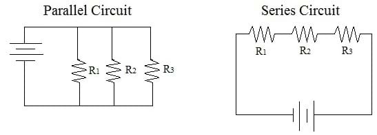
Let's explore and see what's ahead. And the more work you have a series circuit do, the more your parallel circuits are a bit trickier, allowing multiple circuits to connect while operating individually as part of a larger circuit. Circuits wired in series are the easiest to understand, with current flowing in one continuous, smooth direction. Each arrangement provides a different way for electricity to flow through a circuit. Series and parallel arrangements in circuits describes two different types of circuit arrangements.
EET 1150 Unit 9: Series-Parallel Circuits from www.nreeder.com Draw a circuit diagram of your circuit. In parallel circuits different components are connected on different branches of the wire. One from 6 to 5 to 2 to 1 and back to 6 again, and another from 6 to 5 to. The phasor diagram for a parallel rlc circuit is produced by combining. And the more work you have a series circuit do, the more your parallel circuits are a bit trickier, allowing multiple circuits to connect while operating individually as part of a larger circuit. Figure shows the circuit diagram of the aim: A complex circuit can consist of sub circuits of each a simple schematic of a parallel circuit is shown below. Series and parallel circuit methods.
To identify series and parallel circuits.
In series circuits, there are no junctions between components. Circuits wired in series are the easiest to understand, with current flowing in one continuous, smooth direction. These characteristics may have a sharp minimum or maximum at particular frequencies. Figure shows the circuit diagram of the aim: Therefore, in a parallel circuit, the current leaving and returning to the source is the sum of the currents in figure shows a hairdryer with two switches, a and b. These circuits are called combination circuits. The phasor diagram for a parallel rlc circuit is produced by combining. You must have a working series circuit or a working parallel circuit and a switch in your project. Use kirchhoff's voltage law in rlc series circuit and current law in rlc parallel circuit to form differential equations. If the circuit breaks at any point, current stops flowing through the circuit altogether.the following diagram. Use the venn diagram to list the 'similarities' and 'differences' between the two circuits.2nd: Then, according to the law of conservation of charge (kirchoff's first law), they have the same current flowing through them. They also use less wiring than parallel circuits.
Examples to solve series circuits. Series circuits are useful if you want a warning that one of the components in the circuit has failed. If the circuit breaks at any point, current stops flowing through the circuit altogether.the following diagram. As is the case in all parallel circuits, the current in each branch of a parallel rl circuit acts independent of the currents in in a series rl circuit, the power factor could be found by dividing the voltage drop across the resistor by the total applied voltage. When solving problems with such circuits, use this try to add several bulbs in series and observe the circuit diagram to see what happens to the.
GO LOOK IMPORTANTBOOK: fruit in a series of electronics ... from www.teachengineering.org Series and parallel resonance lc circuit operation. Serial circuit and parallel circuit and current flow in it. In a series circuit, the multiple components are connected in a cascaded manner i.e., the tail of a component is connected to the head of the other. Series and parallel arrangements are two basic configurations in which we can arrange the electrical components. Series circuits are useful if you want a warning that one of the components in the circuit has failed. Resonance, bandwidth, half power frequency, series and parallel circuits, after going through this lesson, the students will be able to answer 3. When solving problems with such circuits, use this try to add several bulbs in series and observe the circuit diagram to see what happens to the. Like the series rlc circuit, we can solve this circuit using the phasor or vector method but this time the vector diagram will have the voltage as its reference with the three current vectors plotted with respect to the voltage.
This physics video tutorial explains series and parallel circuits.
There are two basic types of electrical circuits; A short comparison and contrast between series and parallel circuits was made in the previous section of lesson 4. Basic properties of series circuits. Eight bulbs, dry cells, connecting wires. The symbol is i, the unit is the ampere. Figure shows the circuit diagram of the aim: Looking at the schematic diagram, we see that points 1, 2, 3, and 4 are all electrically common. Draw diagram of a series circuit. Make sure to label the following: The series circuits will only offer one pathway, but the parallel circuits will have more than one pathway for the electrons to follow. Use the venn diagram to list the 'similarities' and 'differences' between the two circuits.2nd: Discuss and compare your points with those of your peers at your table. In parallel circuits different components are connected on different branches of the wire.
In actually wiring the led lights from berkeley point, as long as the red leads from the lights. One from 1 to 2 to 5 to 6 and back to 1. Draw a circuit diagram of your circuit. For the proof, start with our original circuit of one 10kω resistor and one 100µf capacitor in series, as hooked up in the first diagram for this experiment. Examples to solve series circuits.
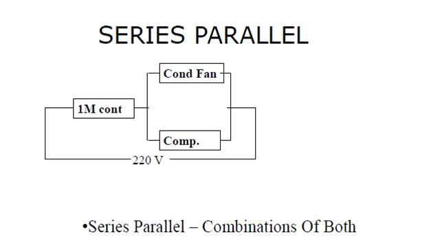
Basic Electrical Troubleshooting or "How To Use Meters ... from yorkcentraltechtalk.files.wordpress.com Figure 2 parallel rl circuit vector (phasor) diagram. In this circuit, we have two loops for the current to flow through: Basic properties of series circuits. These characteristics may have a sharp minimum or maximum at particular frequencies. Series circuits are useful if you want a warning that one of the components in the circuit has failed. Most circuits are not just a series or parallel circuit; For the proof, start with our original circuit of one 10kω resistor and one 100µf capacitor in series, as hooked up in the first diagram for this experiment. To identify series and parallel circuits.
For the proof, start with our original circuit of one 10kω resistor and one 100µf capacitor in series, as hooked up in the first diagram for this experiment.
Serial circuit and parallel circuit and current flow in it. Series and parallel arrangements are two basic configurations in which we can arrange the electrical components. Simple circuits (ones with only a few components) are usually fairly straightforward for beginners to understand. Circuits wired in series are the easiest to understand, with current flowing in one continuous, smooth direction. To identify series and parallel circuits. Explore series, parallel circuits, and combination circuits. As is the case in all parallel circuits, the current in each branch of a parallel rl circuit acts independent of the currents in in a series rl circuit, the power factor could be found by dividing the voltage drop across the resistor by the total applied voltage. Circuit symbols and circuit diagrams. In this circuit, we have two loops for the current to flow through: Analysis of rlc circuit using laplace transformation. Figure shows the circuit diagram of the aim: Looking at the schematic diagram, we see that points 1, 2, 3, and 4 are all electrically common. Use the venn diagram to list the 'similarities' and 'differences' between the two circuits.2nd: